Following the PCB IPC standard for PCB laminate selection enables engineers to more easily identify suitable dielectric materials for rigid, high-speed, and flexible circuit boards. Standards such as IPC-4101, IPC-4103, and IPC-4202 establish clear specifications for critical parameters including impedance control, thermal performance, and durability.
Using these standards as selection guidelines allows designers to confidently choose materials that meet both functional requirements and manufacturing feasibility. Additionally, adopting unified standards helps effectively communicate technical requirements and ensures selected materials fully comply with specific application scenarios.
Key Standards Overview for PCB IPC standard
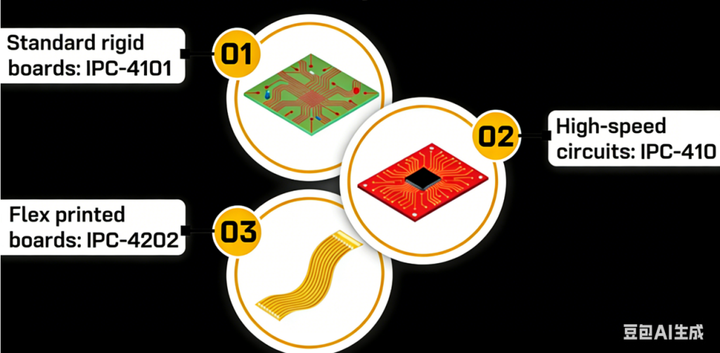
- IPC-4101 provides specification guidelines for rigid and multilayer PCB base materials
- IPC-4103 specifically addresses high-speed laminates for RF/microwave and digital circuits
- IPC-4202 defines requirements for flexible dielectric materials used in both dynamic and static applications
Through this article, you will gain a systematic understanding of key IPC standards for PCB laminates and practical considerations when selecting dielectric materials for your design
1.Key PCB IPC-standard for Selecting Circuit Board Materials
Choosing appropriate dielectric materials is crucial to guarantee the electrical performance, thermal stability, and mechanical reliability of printed circuit boards. To establish unified benchmarks for material performance, IPC has formulated a set of standards that clearly define material characteristics, verification methods, and documentation specifications.
These standards facilitate clear alignment among designers, manufacturers, and suppliers regarding specific material requirements, ensuring that each design’s performance objectives are met
1.1 PCB IPC standard-4101 Specification for Rigid and Multilayer PCB Base Materials
This standard serves as the primary guideline for selecting core and prepreg materials used in rigid printed circuit board manufacturing. It establishes a slash sheet classification system that defines specific material types along with their required technical parameters and performance characteristics.
Understanding the Slash Sheet System in IPC-4101
The standard implements a detailed numbering system that precisely outlines material requirements and performance criteria. This systematic approach ensures manufacturing consistency across different suppliers while eliminating potential ambiguities in laminate specifications.
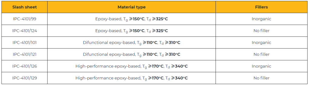
When documenting material requirements in design specifications, engineers should reference the appropriate IPC slash sheet designations rather than using specific commercial product names. For instance, the IPC-4101/126 specification covers detailed technical requirements for woven E-glass reinforced epoxy laminates and compatible prepreg materials.
Lead-Free laminates in IPC-4101
The transition to lead-free soldering processes necessitates the use of materials with enhanced thermal performance characteristics to withstand higher processing temperature requirements.
Table 1: IPC-4101 Slash Sheets and Corresponding Material Classifications
Material Tests Defined by PCB IPC standard-4101
IPC-4101 establishes test methods for material qualification, ensuring consistent evaluation across different suppliers. These tests cover:
- Thermal analysis to determine Tg and Td
- Time-to-delamination tests at multiple temperatures
- Evaluation of physical and mechanical properties
- Environmental stress testing
Selecting materials certified to IPC-4101 guarantees that they have passed rigorous testing and comply with strict industry specifications.
1.2 IPC standard-4103 for High-Speed and RF Laminates
IPC-4103 specifies materials designed for high-speed signal transmission and RF/microwave printed circuit boards. This standard covers both clad and unclad plastic laminates as well as bonding layer materials.
Laminates qualified to IPC-4103 are recognized for their controlled dielectric properties and superior high-frequency performance.
Key Considerations for Selecting High-Speed Materials
To ensure reliable operation, high-frequency materials must exhibit stable electrical characteristics across their intended frequency band. When choosing these materials according to IPC laminate standards, the following factors should be evaluated:
Dielectric Constant Stability: Laminates qualified to IPC-4103 standards, such as Rogers RO4350B or Isola Tachyon 100G, demonstrate minimal variation in dielectric constant, typically within ±0.05 across the frequency range of 1 to 20 GHz.
Dissipation Factor: A lower dissipation factor (approximately 0.004) helps reduce signal loss at high frequencies. For instance, Panasonic Megtron 6 exhibits a dissipation factor of about 0.0022 at 10 GHz, making it well-suited for high-speed design applications.
Controlled Impedance Capability: Materials selected for controlled impedance designs must provide tight dielectric constant tolerances, low dissipation factor, and uniform thickness consistency across all layers. This consistency helps prevent impedance mismatch, which can cause signal reflection, distortion, or loss.
Isotropic Properties: Isotropy refers to a material’s mechanical, thermal, and electrical characteristics remaining uniform in all directions (x, y, and z axes). Highly isotropic materials, such as PTFE laminates, deliver more predictable and reliable performance under varying environmental and electrical conditions.
1.3 IPC standard-4202 for Flexible Dielectrics
IPC-4202 establishes the requirements for flexible dielectric materials utilized in flexible and rigid-flex printed circuit boards.
In contrast to rigid laminates, flexible substrates need to endure repeated mechanical stress, bending, and folding operations while preserving their electrical integrity.
This standard specifies both the specifications and test methodologies to guarantee that these materials provide mechanical flexibility, thermal stability, and reliable electrical performance across various applications.
Slash-Sheet System in IPC standard-4202
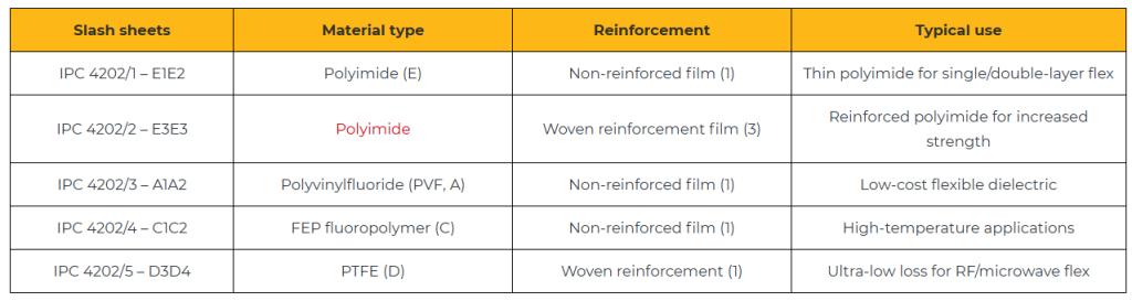
Similar to IPC-4101, IPC-4202 utilizes a slash-sheet system to categorize specific material types. Below are some examples of slash sheets along with their common applications:
Table 2: IPC-4202 Flexible Base Dielectric Materials
Understanding Slash Sheet Codes in IPC-4202
The typical format for a slash sheet code is as follows:
IPC-4202/ – <dielectric><reinforcement><reinforcement type><thickness>
Where each component is defined as:
- Dielectric type (alphabetic codes):
A = PVF, B = PET, C = FEP, D = PTFE, E = polyimide - Reinforcement (numeric codes):
1 = non-reinforced, 2 = nonwoven, 3 = woven, 4 = combination woven + nonwoven - Reinforcement type (alphabetic codes):
A = glass, B = polyester, C = aramid, etc. - Thickness (numeric codes):
2 = 50 μm, 1 = 25 μm, etc.
Example Analysis: IPC-4202/ – B2B2
This code represents: Nonwoven polyester-reinforced PET with 50 μm thickness
- Dielectric: PET (code B)
- Reinforcement method: nonwoven (code 2)
- Reinforcement type: polyester (code B)
- Thickness: 50 μm (code 2)
Key Criteria for Selecting Flexible Dielectric Materials
IPC-4202 defines essential material properties to guarantee reliability in demanding dynamic applications. These critical parameters include:
- Elongation and Flexibility: Flexible laminates must demonstrate elongation exceeding 30% to endure repeated bending cycles.
- Peel Strength: A minimum peel strength of 6 lbs/inch is required to prevent delamination when subjected to mechanical stress.
- Dimensional Stability: Materials should exhibit less than 0.1% shrinkage during thermal cycling to ensure proper trace alignment.
- Thermal Endurance: Materials need to withstand elevated soldering temperatures without experiencing cracking, curling, or delamination.
Testing and Qualification Procedures
IPC-4202 incorporates IPC-TM-650 test methodologies to assess:
- Flexural endurance performance (through bend and crease testing)
- Copper foil peel strength characteristics
- Moisture absorption properties and resistance
- Dielectric breakdown voltage capability
- Dimensional stability under thermal cycling conditions
These tests simulate real-world stress conditions, ensuring that flexible circuits can perform reliably in wearables, foldable electronics, medical devices, and aerospace systems.
For more on flex PCB testing, see IPC standards and guidelines for flex PCBs.
2. What are the factors that impact PCB material reliability?
When choosing materials, fundamental properties like DkDk, DfDf, TgTg, and CTE are just the beginning. Advanced applications require a deep understanding of how a material behaves under specific operating conditions.
This includes signal integrity at high frequencies, thermal cycling reliability, manufacturability for complex designs, and compliance with environmental standards like RoHS and REACH. These concepts are discussed below.
2.1 Electrical behavior at high speeds for PCB IPC-standard
Above 5 GHz, materials must maintain stable electrical properties and low loss to preserve signal integrity
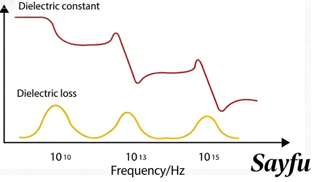
DkDk variation with frequency
Lower Dk values (below 3.5) help minimize signal distortion. Materials need to maintain consistent Dk across broad frequency ranges, as variations can lead to phase distortion and signal timing errors.
Df Characteristics at GHz Frequencies
Materials with higher dissipation factors (such as standard FR-4 with Df ≈0.02) contribute to increased signal attenuation. For RF and microwave applications, materials with Df below 0.005 are generally preferred to minimize signal loss.
The IPC-4101 slash sheet system specifies both Dk and Df values at standardized test frequencies (typically 1 MHz, 1 GHz, or 10 GHz).
For instance: IPC-4101/126 requires Dk ≤3.7 and Df ≤0.009 when measured at 1 GHz.
Impact of Copper Surface Profile on Signal Integrity
Copper foil with rough surface texture can significantly increase insertion loss, particularly at higher operating frequencies. IPC-4562 standards recommend using very low profile (VLP) copper foils for high-speed printed circuit board applications. For more PCB,visit www.sfmpcb.com
2.2 Thermal Stability in Extreme Conditions
In high-temperature environments, PCB materials must maintain their mechanical and electrical integrity under prolonged thermal stress. As a result, properties such as thermal conductivity (k), glass transition temperature (T_g), decomposition temperature (T_d), and coefficient of thermal expansion (CTE) become particularly critical.
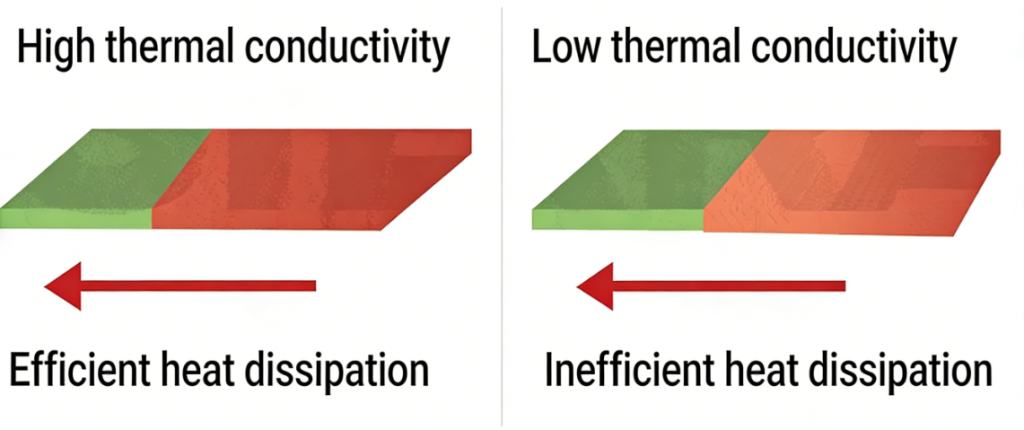
Thermal Conductivity for Power-Intensive Applications
Materials with higher thermal conductivity (e.g., metal-core PCBs or ceramic-filled laminates) are preferred in power electronics.
While IPC standards for PCB materials do not specify a minimum thermal conductivity requirement, materials with a k-value greater than 1 W/m·K (e.g., ceramic-filled laminates) are well-suited for applications such as motor drives, power supplies, or automotive ECUs.
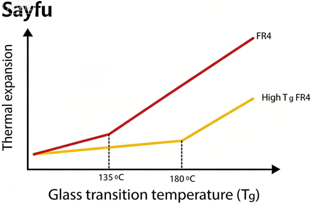
Tg, Td, and Lead-Free Compatibility
High-Tg materials (typically above 180°C) are essential for PCBs operating in harsh environments or undergoing lead-free soldering processes. IPC-4101 defines standard Tg testing methods, including dynamic mechanical analysis and thermomechanical analysis.
Td indicates thermal reliability and should exceed 300°C to withstand lead-free solder reflow processes with peak temperatures of 260°C. IPC-4101 and IPC-4103 provide reference Td values measured using thermogravimetric analysis (TGA).
The IPC-4101 standard also specifies key thermal tolerance parameters such as T260, T288, and T300, representing the maximum duration a material can withstand these respective temperatures without experiencing significant degradation.
CTE and Solder Joint Reliability
Mismatched coefficients of thermal expansion (CTE) induce stress on solder joints during temperature cycling, particularly in multilayer circuit boards. The CTE along the X and Y axes should closely match that of copper (approximately 17 ppm/°C), while the Z-axis CTE must be maintained at a low level to prevent plated through-hole (PTH) failures.
IPC-4101 recommends measuring CTE in all three principal directions. Specifically, the Z-axis CTE should remain below 70 ppm/°C within the temperature range of 50–260°C to ensure plated through-hole integrity and minimize barrel cracking.
2.3 Manufacturing Compatibility
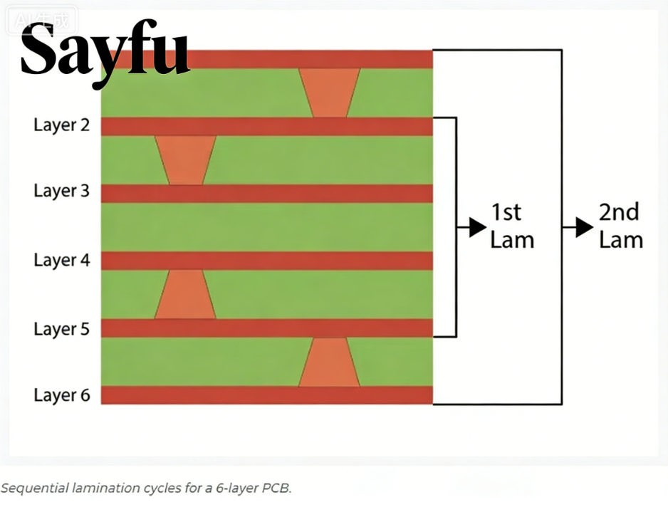
Sequential Lamination
IPC-4101 specifies that materials must maintain stable Tg and consistent flow characteristics during sequential lamination cycles (typically 2-3 cycles for HDI designs). No-flow prepregs should be qualified under IPC-4101/43 or IPC-4101/26 standards to ensure reliable rigid-flex bonding.
Dielectric Thickness Control
The chosen material must maintain dimensional stability during lamination processes to ensure consistent impedance performance. According to IPC-4101 specifications, core thickness tolerance is defined as ±10%, while prepreg thickness tolerance is maintained within ±15%.
2.4 RoHS/REACH and UL Compliance
High-reliability designs require materials to comply with UL 94V-0 flammability standards. To meet EU regulatory requirements, halogen-free PCB materials are specified in IPC-4101B sheets. Material traceability and auditability are governed by the IPC-1752 standard.
Sayfu Circuits provides rapid fabrication and assembly services for high-quality circuit boards. Additional details can be found in our rigid PCB manufacturing capabilities section.
2.5 Testing and Quality Control
Standardized testing procedures for dielectric breakdown, peel strength, thermal shock, and moisture resistance are established in IPC-TM-650.
In multilayer board construction, all layer types (core and prepreg) must satisfy the relevant IPC-4101/4202 specifications. Laminate flow consistency verification is conducted using IPC-L-107 test coupons.
For design verification guidance, refer to the design for testing guidelines for PCB manufacturing recommendations.
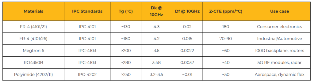
3. Application Examples of PCB Materials and Their Comparisons
Table 3: Comparison of Common PCB Materials and Their Applications
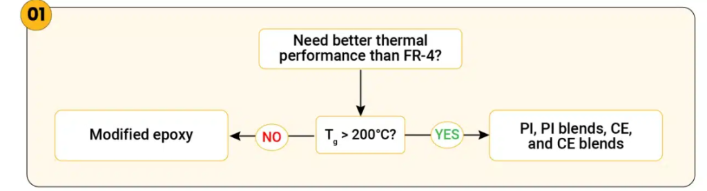
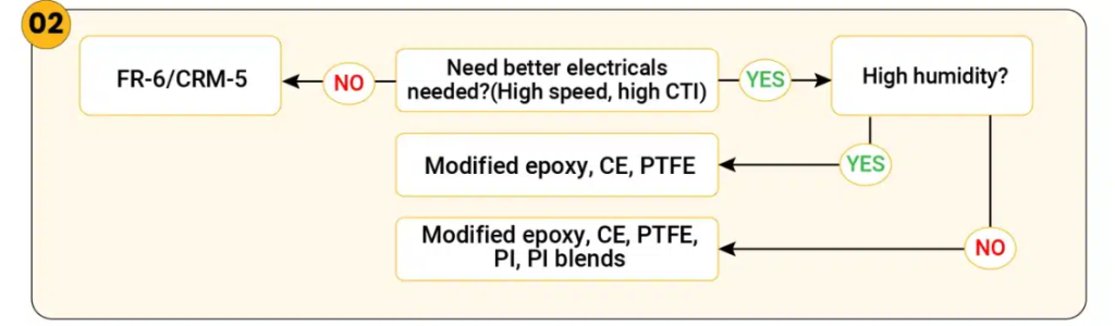
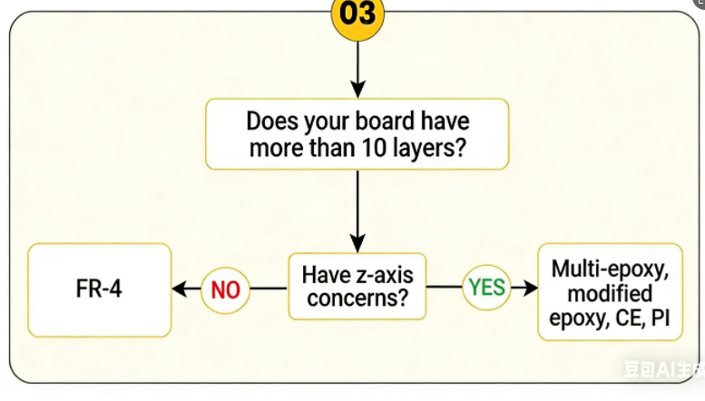
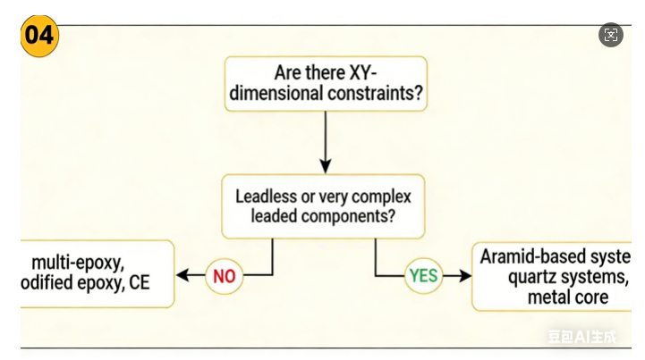
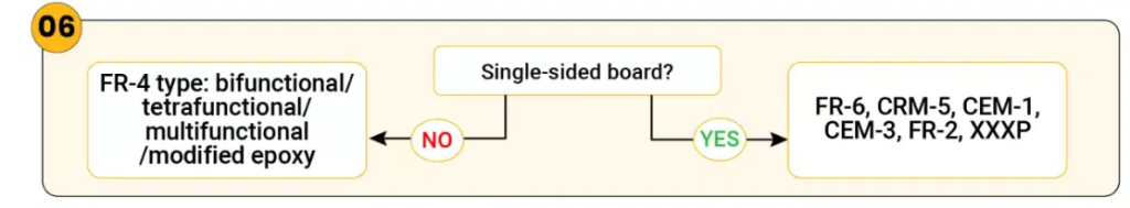
4. Flowcharts for Selecting Optimal Circuit Board Base Materials
We have developed six streamlined flowcharts in accordance with IPC standards for PCB laminate selection. These charts address key design considerations including thermal performance, electrical characteristics, layer count requirements, dimensional stability, hole plating specifications, and single-sided board applications.
1: Laminates with Enhanced Thermal Performance
2: Materials for Superior Electrical Properties
3: Substrates Supporting Designs Exceeding 10 Layers
4: Boards Demanding Improved Dimensional Stability
5: PCBs Utilizing Punch-Plated Through Holes
6: Dielectric Materials for Single-Sided Board Construction

Key Takeaways for PCB IPC-standard
- When selecting materials for your designs, consistently adhere to IPC standards for PCB laminates. While considering key material parameters (Dₖ, Df, Tg, Td, CTE), always verify performance under actual operating conditions.
- Align material characteristics with specific application requirements: high-speed, high-power, or dynamic flex applications.
- For guaranteed consistency and compliance, reference IPC slash sheets rather than relying solely on vendor brand names.
- Verify all testing results, certification status, and environmental compliance before finalizing your laminate selection.
Choosing the appropriate PCB material extends beyond reviewing datasheets; it demands careful alignment of electrical, thermal, and mechanical properties with application requirements. IPC-4101, IPC-4103, and IPC-4202 establish the fundamental framework for making reliable and compliant material decisions. Adherence to these standards ensures your PCB design achieves consistent performance and sustained long-term reliability.
Need assistance determining which IPC standard to implement? Submit your questions through Sayfu, where our PCB specialists will provide detailed responses.