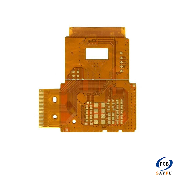
Double-Sided Thin FPC with Embossing for Compact Electronics
Images
General Specification:
0.1mm, H/Hoz copper, thickness: 0.10mm;
Min trace width/space: 3/3mil;
Min hole size: 0.3mm;
Surface finish: ENIG
Application: set top box, floppy driver, manostat, big power etc.
This double-sided thin FPC with embossing is intended for compact electronics that need more routing freedom than a single-sided flex circuit can provide. The 0.10 mm profile, 3/3 mil trace width and spacing, 0.3 mm minimum hole size, and ENIG finish suit a small interconnect that must fit around other parts of the assembly.
The second copper side gives the layout another path for signals and connections. That can simplify an interconnect where a one-layer design would need crossovers, extra board area, or a separate cable. The embossed feature is part of the mechanical definition of this product, so its location and dimensions need to be included with the board outline and assembly drawings.
Product Overview
Double-sided flex is a good fit when a product has limited space but the connection pattern cannot be completed cleanly on one conductor layer. It can link displays, controls, power sections, and small modules without adding a rigid interposer or a loose wire harness. The thin construction is useful when the circuit must pass through a narrow section of the enclosure or sit close to adjacent assemblies.
This board is not simply a thinner rigid PCB. The mechanical path is part of the design. The finished outline, the position of the embossed area, the connector end, and the intended bend path need to match the installed product. For projects that require a different board structure, see the FPC PCB product category for related flexible circuit options.
Routing and Mechanical Layout
The 3/3 mil routing and 0.3 mm minimum hole size support a compact connection pattern. Pad layout, hole locations, copper clearance, and coverlay openings still need to suit the actual connector or soldering method. Include the component drawing or connector drawing with the RFQ when the termination area is tight or has a defined orientation.
The bend section and the connection section serve different purposes. Keep bend-related requirements in the mechanical information, and show the connector position, pad support, coverlay openings, and any stiffener requirement in the production drawing. That allows the connection area to be reviewed before fabrication.
Embossed Area and Assembly Fit
The embossed area should be identified clearly in the supplied mechanical drawing. Its dimensions, position, and relationship to the FPC outline, copper pattern, and connection areas need to be clear before the board is quoted. That prevents the formed feature from being treated as an undefined detail after the electrical layout is complete.
ENIG is specified for the exposed pads on this product. For a circuit that connects to a display, control assembly, or other compact module, the pad size and coverlay opening need to match the selected component or connector. If the FPC will be supplied with mounted parts, connectors, or additional inspection, include those requirements with the quotation files. The turnkey PCB assembly page describes the available support for fabrication-and-assembly projects.
Applications
Typical applications for this double-sided thin FPC include set-top boxes, floppy drives, pressure controllers, high-power equipment, and other compact electronic products with a defined flexible connection.
It can also be considered where the installation needs two-sided routing in a narrow space and the flex path and connection method are already defined in the design files.
What to Confirm Before Production
For quotation, provide Gerber files, drill files, an FPC stack-up drawing, and mechanical notes. The package should include the finished outline, embossed-area drawing, bend direction or movement requirement, coverlay details, connector or stiffener drawings, requested quantity, application, and any inspection requirement. With these details, the electrical pattern and mechanical fit can be reviewed together instead of as separate assumptions.
Quotation Information
If the product includes a defined assembly sequence, component installation, or special packaging requirement, add that information to the RFQ as well. It gives the quotation a clearer basis and reduces follow-up work after the board outline and connection areas have been set.