Aluminum Metal Core PCB for LED Light Applications
Images
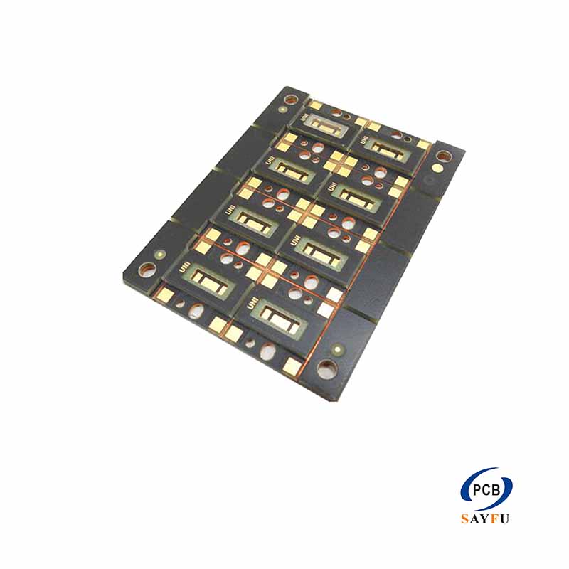
General Specification:
Metal core PCB
Thickness: 1.6mm
Materials: Aluminium
Surface treatment: PB-LEAD FREE
Sold mask: White
Min line/space: 0.2mm
Min Hole: 0.3mm
Application: LED light
This aluminum metal core PCB is specified for LED light applications with a 1.6 mm board thickness, white solder mask, lead-free HASL, 0.2 mm minimum line and spacing, and a 0.3 mm minimum hole. It is intended for a defined LED board layout that uses an aluminum-backed construction.
The electrical layout, component placement, and mechanical installation need to be developed together. An LED board often fits inside a housing, reflector, channel, or heat-sink assembly. The finished outline, mounting pattern, connector position, and available clearance therefore need to match the product around the PCB.
Product Overview
The aluminum material and 1.6 mm thickness form the basic construction of this board. The specification does not state a thermal conductivity value or dielectric-layer thickness, so those properties should not be inferred from the product type. Projects that depend on a particular thermal target need the required material information in the RFQ.
The 0.2 mm minimum line and spacing define the stated routing feature for this product. The completed Gerber files still need to show the actual copper pattern, pad geometry, and clearances. A board with a simple LED string may use the space differently from one that also carries connectors, control components, or several lighting zones.
Holes, Outline, and Mounting
The 0.3 mm minimum hole is part of the product specification. Drill data should identify which holes are electrical and which are mechanical. Mounting holes, slots, and cutouts also need to be included in the outline drawing because they affect how the board fits the light assembly.
Where the PCB attaches to a metal housing or heat sink, provide the mating-surface drawing and fixing method. This gives the quotation useful context for the board shape and mounting pattern. It does not replace the need for the customer to define the complete thermal design of the finished product.
Surface Finish and LED Assembly
Lead-free HASL is specified for the exposed pads, with white solder mask over the protected copper. Pad size, solder-mask opening, and component orientation need to match the LED package, connector, and planned soldering process. Polarity marks and reference text should remain clear of pads and optical areas.
For boards supplied with LEDs, connectors, or other components, provide the BOM, placement data, and assembly drawing. The turnkey PCB assembly page provides related information for combined fabrication and assembly work.
Applications
This board is intended for LED light products that need an aluminum metal-core PCB with the stated routing and hole features. It can be considered for light modules, linear lighting, signs, and similar assemblies when the board outline, component selection, and mechanical interface match the final design.
For product families that use several LED counts or connector options, provide the matching Gerber and assembly files for each version. The board material may remain the same while the copper layout, mounting pattern, or component population changes. Identifying those differences at quotation stage keeps the PCB and assembly scope tied to the correct version.
It also prevents component data from one lighting variant being applied to another board version.
For a quotation, provide Gerber files, drill files, the board outline, and LED assembly information. Include the lead-free HASL requirement, white solder mask, quantity, application, and inspection requirements. Related board options are listed under PCB manufacturing capabilities.