12-Layer Rigid-Flex PCB with 2 oz Copper
Images
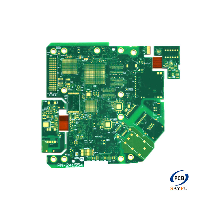
General Specification:
Layer count : 12 layers ;
Material : FR4, PI, PET,and adhesive;
Copper thickness: 2OZ
Coverlay: 1/2mil
Board thickness: 0.07~3.0mm ;
Trace width/space: 3/3.5mil;
Surface finish: Immersion Gold
This 12-layer rigid-flex PCB uses FR4, PI, PET, and adhesive materials with 2 oz copper, 0.5 mil coverlay, 3/3.5 mil trace width and spacing, and immersion gold. The stated board-thickness range is 0.07-3.0 mm, reflecting the different rigid and flexible areas within the construction.
Twelve layers provide substantial routing capacity for a product that needs several component-supporting rigid areas and integrated flexible connections. The exact arrangement of rigid and flex layers is not defined by the layer count alone. A complete stack-up is required to show which layers continue through each section and how the material transitions are built.
Product Overview
FR4 forms the rigid portion of the board, while PI and PET are included in the flexible material set together with adhesive. The final stack-up should identify the material used at each layer and the thickness assigned to every rigid and flex section. The broad 0.07-3.0 mm range should not be treated as one finished thickness for all areas.
The 2 oz copper requirement adds another design consideration. Copper distribution, conductor geometry, and the flex-layer arrangement need to match the electrical design. The product data does not state a current rating, so the customer's circuit and conductor requirements remain the basis for evaluating the layout.
Flex Construction and Coverlay
The flex section uses 0.5 mil coverlay. Coverlay openings, flex outline, connector pads, and any stiffener area need to be defined in the artwork and mechanical drawing. If the flex section bends during operation, provide the intended motion and bend information with the RFQ; no movement-cycle rating is stated for this product.
The installed drawing should show the relative position of the rigid sections and the route taken by the flex. This helps establish flex length, connector orientation, and clearance around other parts of the product. It is especially important when the board is folded into a compact enclosure during assembly.
Dense Routing and Layer Transitions
The specified 3/3.5 mil routing supports a dense multilayer layout. Final line widths, spacing, via locations, and layer transitions need to appear in the completed design files. If the board includes impedance-controlled nets, provide the impedance table and reference-layer information with the stack-up.
Component escape routing and connectors can determine where the rigid-flex transitions occur. Include relevant footprint and connector drawings when they constrain the routing or termination areas. The quotation can then be based on the actual board rather than a generic twelve-layer description.
Surface Finish and Assembly
Immersion gold is specified for exposed pads. Pad geometry, coverlay openings, solder-mask details on rigid areas, and component footprints need to match the assembly process.
For assembled boards, provide the BOM, placement data, assembly drawing, and any special handling information for the flex sections. The turnkey PCB assembly page provides related information for combined fabrication and assembly work.
Applications
This 12-layer rigid-flex construction can be considered for compact electronic assemblies such as mobile devices, computers, displays, controls, and storage equipment when the project needs multilayer routing and flexible interconnection in one board. Application suitability depends on the final stack-up, component layout, flex path, and installed mechanical position.
For a quotation, provide Gerber files, drill files, the 12-layer rigid-flex stack-up, and the installed mechanical drawing. Include the material sequence, copper distribution, coverlay definition, connectors, quantity, application, and inspection requirements. Related rigid-flex context is available on PCB manufacturing capabilities.