4-Layer Rigid-Flex PCB with 2-Layer Flex Section
Images
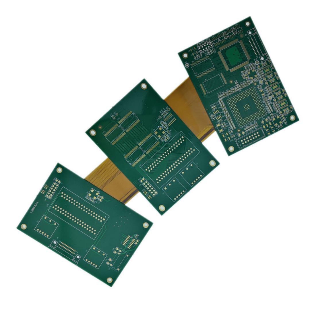
General Specification:
Layer: 4L
Panel size/mm: 80mm*110mm
Material: Rigid-Flex
Finished Thickess:1.6mm
Finished Copper: 35um
Surface treatment: ENIG
Soldermask: Green+CVL
Silkscreen: Black
Special Technology: Rigid part(4 layers), flex part(2 layers)
This 4-layer rigid-flex PCB combines a 4-layer rigid part with a 2-layer flex part. It uses 35 um copper, a 1.6 mm finished rigid-board thickness, ENIG, green solder mask, black silkscreen, and coverlay on the flexible area.
The rigid and flex sections have different mechanical roles but share one electrical design. The rigid area supports components, connectors, and mounting features. The two-layer flex section provides the connection between rigid areas or other assemblies. The outline and flex path need to be planned with the installed product in mind.
Product Overview
The four-layer rigid section provides routing and component support, while the two-layer flex portion keeps the interconnect thin and movable during installation. The final stack-up should show which layers continue into the flex section and how the flex connects to the rigid circuitry.
The 1.6 mm thickness applies to the rigid construction. The mechanical drawing should identify the rigid outlines, flex length, connector positions, and installed orientation. If several rigid sections are connected by the flex, show their relative position in the finished assembly rather than only the flat manufacturing view.
Flex Area and Coverlay
Coverlay is specified for the flex section, while green solder mask is used on the rigid area. The supplied artwork needs to distinguish these materials and define the openings around pads and connection areas. Include any stiffener or supported termination requirement when it affects a connector or soldered interface.
The flex path should also identify whether the circuit bends only during installation or moves in service. The product data does not state a bend radius or movement-cycle rating, so those requirements need to come from the application. An enclosure drawing can clarify available space and the intended bend direction.
Transition and Copper Layout
The transition between rigid and flexible sections is part of the mechanical and electrical design. Copper routing, coverlay boundaries, and component keep-out areas need to follow the actual board layout. The 35 um copper specification should remain in the stack-up and fabrication notes.
Connector footprints and pad geometry are best supplied with the component or connector drawing. This is especially useful where a connector sits close to the rigid-flex transition or controls the orientation of the installed flex section.
ENIG and Assembly Fit
ENIG is specified for the exposed pads. Green solder mask and black silkscreen apply to the rigid area. Pad openings, reference marks, and component orientation need to match the assembly drawing.
For an assembled board, provide the BOM, placement data, assembly drawing, and any handling restrictions for the flex section. The turnkey PCB assembly page provides related information for combined fabrication and assembly projects.
Application Fit
This construction suits compact products that need a four-layer rigid circuit connected through a two-layer flexible section. Final suitability depends on the component layout, flex path, connector orientation, and installed mechanical position.
When the product has more than one folding or installation stage, include that sequence in the mechanical information. It can clarify which rigid section is fixed first and how the flex section reaches its final position.
For a quotation, provide Gerber files, drill files, the rigid-flex stack-up, and the mechanical drawing. Include the coverlay definition, flex path, quantity, application, and inspection requirements. Further structure context is available on PCB manufacturing capabilities.