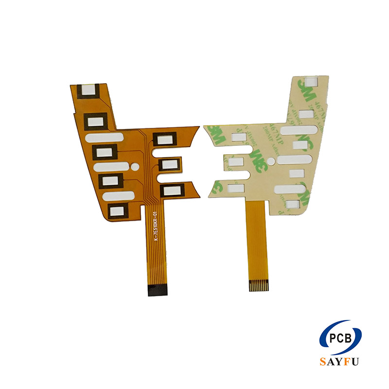
The Differences Between FPC Layout and PCB Layout
FPC Layout, as the core of flexible printed circuit board design, differs significantly from rigid PCB Layout in terms of design concepts, application scenarios, and the stability of the final product performance. Generally speaking, the performance of rigid PCBs in products is usually more stable, and this is mainly due to their physical characteristics and environmental adaptability.
Materials and Structures: The FPC Layout uses flexible polyimide substrate, and the design needs to take into account the dynamic requirements of bending and folding; the PCB Layout is based on the rigid glass fiber substrate (FR-4), with a stable structure.
Design rules: For FPC Layout, the wiring should avoid areas with concentrated bending stress. Curved routing is commonly used, and the protection of bending areas is strengthened. For PCB Layout, it focuses more on optimizing signal integrity and heat dissipation, and the rules are relatively uniform.
Application environment: FPC is used for continuous movement or in confined spaces (such as mobile phone hinges, camera modules); PCB is used in fixed, static harsh environments (such as server motherboards, industrial control power supplies).
Distinction:
The reason why rigid PCBs have more stable performance is as follows: Their hard substrate provides excellent mechanical strength and dimensional stability, effectively resisting external force deformation and vibration. At the same time, it has better heat management capabilities, which can quickly dissipate the heat generated by the chips through the large-area copper layer and heat dissipation holes, avoiding performance degradation caused by high temperatures. Moreover, its mature manufacturing process and robust structure make it more reliable in harsh environments such as high temperatures and high humidity. However, FPC may have the risk of conductor fatigue fracture during repeated bending, and its thermal expansion coefficient is also difficult to perfectly match with the welded components, presenting more challenges in long-term reliability.
Therefore, in fixed-installation products that aim for extreme stability, rigid PCBs are the better choice; FPC is another high-performance solution designed to achieve the thinness and flexibility of equipment, and its stability is reflected in the field of dynamic flexibility.