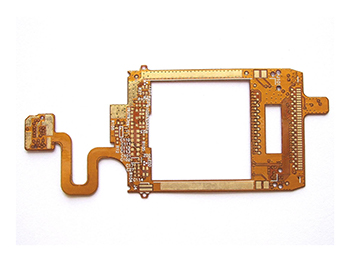
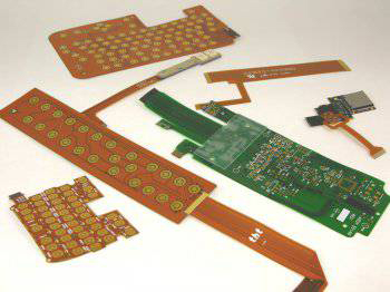
FPC flexible circuit boards are used in smart car electronics when a connection must fit through a tight space, bend during assembly, or reduce the wiring burden between modules. The useful question is not whether FPC is "advanced," but whether a flexible circuit solves a real packaging, routing, or assembly problem without adding avoidable reliability risk.
Where FPC Fits in Smart Car Electronics
An FPC is a flexible printed circuit board. In automotive electronics, it can be used as an interconnect for modules such as battery management systems, camera modules, lighting assemblies, door control units, infotainment displays, instrument clusters, electronic control units, wireless charging modules, and solar-related electronics. These applications do not all need the same FPC structure. A display connection, a camera module, and a battery sensing circuit may have different requirements for bending, shielding, connector design, and inspection.
For broader background on flexible board applications, the related article on automotive flexible circuit board market analysis gives useful context. The current article focuses more narrowly on what should be checked before an FPC is selected for a smart car product.
What FPC Solves Compared With Rigid Wiring
FPC is usually considered when a rigid PCB, cable harness, or connector-heavy layout creates too much space, weight, or assembly complexity. A flexible circuit can route signals through a folded or curved area and can reduce the number of separate interconnect parts. This can help in compact modules where the enclosure shape is already fixed.
The trade-off is that the flexible area becomes part of the reliability design. The bend radius, copper layout, coverlay opening, stiffener position, and connector area must be reviewed together. A circuit that looks acceptable in a flat drawing can still fail if the bend zone carries stress through copper traces, solder joints, or transition areas.
Design Checks Before the Stackup Is Fixed
The first design check is whether the flex area is static or dynamic. A static bend may only need to survive installation and service handling. A dynamic bend needs a more conservative review because repeated movement can expose copper fatigue, adhesive stress, and connector strain. These two cases should not be treated as the same requirement.
Material selection also matters. Polyimide-based flexible circuits, adhesive systems, copper type, coverlay, stiffeners, and surface finish all affect manufacturability and long-term behavior. The exact material system should be confirmed with the PCB manufacturer instead of being selected only from a generic drawing note. For related material context, see PCB substrate materials and raw materials.
Signal requirements should be reviewed early. If the FPC carries high-speed, RF, camera, or display signals, the designer may need controlled impedance, reference planes, shielding, or tighter connector planning. If the FPC only carries low-speed control or power signals, a simpler structure may be suitable. The decision depends on the circuit function, not on the name "FPC" alone.
Manufacturing and Assembly Risks
Several FPC problems appear at the transition between flexible and rigid or reinforced areas. Pads, connectors, stiffeners, and soldered components should not be placed where bending stress is concentrated. The layout should leave enough room for handling, fixture support, and inspection during assembly.
Assembly conditions should also be confirmed. Some FPC designs need stiffeners to support connector mating or SMT placement. Others may need specific panelization, carrier support, or handling instructions. If the product requires a combination of flexible and rigid board areas, the article on rigid-flex circuit board design is a useful related reference.
Testing should match the function of the circuit. A simple continuity test may be enough for a low-complexity interconnect, but it does not prove signal integrity, connector reliability, or bend durability. The test plan should be discussed before the design is released, especially when the FPC is hidden inside a module after assembly.
What to Confirm Before Quotation
Before requesting a quotation, the buyer or engineer should provide enough information for the manufacturer to judge the real design risk:
- Where the FPC will be used in the product
- Whether the bend is static or dynamic
- Expected bend location and mechanical envelope
- Stackup, copper weight, material preference, and surface finish if known
- Connector, stiffener, and component placement requirements
- Signal type, impedance needs, or shielding requirements
- Assembly method and inspection requirements
- Environmental or reliability requirements that the product must meet
This information helps avoid treating all flexible circuits as the same product. In practice, an FPC for a simple display connection, an automotive camera module, and a battery management circuit may require different design reviews even if the basic board type is similar.
FPC flexible circuit boards can be a practical choice for smart car electronics when space, movement, or assembly routing makes a rigid solution inefficient. The design should be selected through bending, material, stackup, assembly, and testing checks rather than through a general claim that flexible circuits are lighter or more reliable.